Home
/ 555 Timer Schematic : 555 Timer Circuits Home Facebook - 500ms is the same as saying 0.5s so by rearranging the formula above, we get the calculated value for the resistor, r as:
555 Timer Schematic : 555 Timer Circuits Home Facebook - 500ms is the same as saying 0.5s so by rearranging the formula above, we get the calculated value for the resistor, r as:
555 Timer Schematic : 555 Timer Circuits Home Facebook - 500ms is the same as saying 0.5s so by rearranging the formula above, we get the calculated value for the resistor, r as:. Derivatives provide two or four timing circuits in one package.it was commercialized in 1972 by signetics. Call or request a quote now! A monostable 555 timer is required to produce a time delay within a circuit. In this category, we have handpicked some really useful 555 timer circuits which will be interesting to electronics engineering students and hobbyists alike. This tutorial provides sample circuits to set up a 555 timer in monostable, astable, and bistable modes as well as an in depth discussion of how the 555 timer works and how to choose components to use with it.
Figure 2 shows the basic 555 timer monostable circuit. Daman shah june 5, 2021. Here, with the help of the 555 timer ic, we are eliminating the need of manually switching on or off the device. 555 datasheet 555 duty cycle 555 metronome 555 reset function 555 time delay relay inverted 555 timer pulse generator. A collection of 555 circuits using the 555 timer as an astable oscillator with different duty cycles.
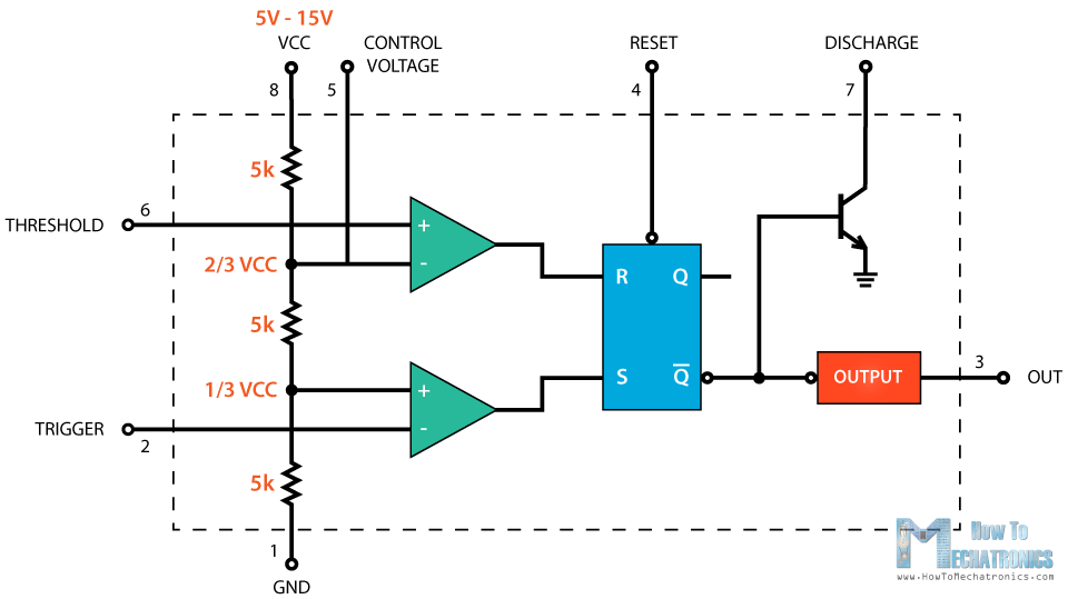
555 Timer Ic Working Principle Block Diagram Circuit Schematics from howtomechatronics.com The time intervals can be used for keeping a relay controlled load on or activated for the desired amount of time and an automatic switch off once the delay period. Call or request a quote now! Daman shah june 5, 2021. Pin 8, which is the power supply pin, v cc, gets connected to +9vdc. To understand the basic concept of the timer let' s first examine the timer in block form as in figure 1. Timer, op amp, and optoelectronic circuits & projects. Lm555 timer 1 features 3 description the lm555 is a highly stable device for generating 1• direct replacement for se555/ne555 accurate time delays or oscillation. The 555 timer is a simple integrated circuit that can be used to make many different electronic circuits.
Being an integral part of electronics project, 555 timer ic is very often used in simple to complex electronics projects.
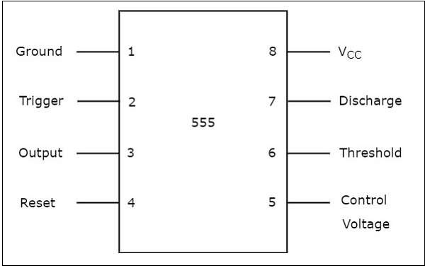
If you want to know all the pinout of the 555 timer, what each pin is and what each pin does, see 555 timer pinout. The time intervals can be used for keeping a relay controlled load on or activated for the desired amount of time and an automatic switch off once the delay period. Once this switch is pushed, the circuit pulls its output to a. The circuit operates on 9vdc of power. The 555 is also very versatile, and can be used. This tutorial provides sample circuits to set up a 555 timer in monostable, astable, and bistable modes as well as an in depth discussion of how the 555 timer works and how to choose components to use with it. Referring to the timing diagram in figure 3, a low voltage pulse applied to the trigger input (pin 2) causes the output voltage at pin 3 to go from low to high. The working modes of a 555 timer are astable, bistable, and monostable. There are simple circuits for beginners and advanced engineers. Figure 1 is the pinout and functional block diagram for the 555 timer ic. 555 timer is an industrial standard ic existing from early days of ic. With this information you will learn how how the 555 works and will have the experience to build some of the circuits below. New, used, and refurbished mro & automation parts for sale at discounted prices.
A collection of 555 circuits using the 555 timer as an astable oscillator with different duty cycles. The circuit operates on 9vdc of power. This led will be switched on when button s1 is pressed and switched off when button s2 is pressed. So the power line is 9v. The second 555 timer helper will extend the timers output duration without having to use large values of r1 and/or c1.
Cannot Understand The 555 Ic Reset Electrical Engineering Stack Exchange from i.stack.imgur.com For a great resource on the 555 timer, opamps, and other ic's check out the engineer's mini notebook: The 555 timer is a chip that can be us… The output voltage from the chip is around 1.5 v lower than vcc when high and around 0 v when low. The 555 is also very versatile, and can be used. Adjustable on off timer(using 555 astable mode) in this circuit a timer with cyclic on off operations is designed. Here, with the help of the 555 timer ic, we are eliminating the need of manually switching on or off the device. The second 555 timer helper will extend the timers output duration without having to use large values of r1 and/or c1. This circuit uses very basic components like 555 timer and 4017 counter.
We have a large collection of simple and advanced projects using 555 timer ic.
555 timer is an industrial standard ic existing from early days of ic. The above schematic shows the 555 timer bistable multivibrator circuit. Simple 555 timer circuits & projects. Lm555 timer 1 features 3 description the lm555 is a highly stable device for generating 1• direct replacement for se555/ne555 accurate time delays or oscillation. The breadboard schematic of the above circuit is shown below. From our earlier discussions we know that for a 555 in the delay timer mode, the delay could be accurately managed through a single external resistor and one capacitor. There are simple circuits for beginners and advanced engineers. Here is the practical demonstration of the bistable mode of 555 timer ic, where we have connected a led to the output of the 555 ic. The output voltage from the chip is around 1.5 v lower than vcc when high and around 0 v when low. 555 datasheet 555 duty cycle 555 metronome 555 reset function 555 time delay relay inverted 555 timer pulse generator. Adjustable on off timer(using 555 astable mode) in this circuit a timer with cyclic on off operations is designed. Figure 2 shows the basic 555 timer monostable circuit. We have siemens parts in stock and ready to ship.
The circuits explained here are 10 best small timer circuits using the versatile chip ic 555, which generates predetermined time intervals in response to momentary input triggers. 555 timer was first introduced by signetics corporation in 1971 as se555/ne555. There are simple circuits for beginners and advanced engineers. Basic 555 monostable multivibrator circuit. The above schematic shows the 555 timer bistable multivibrator circuit.
555 Timer Tutorialspoint from www.tutorialspoint.com The 555 timer ic is an integrated circuit (chip) used in a variety of timer, delay, pulse generation, and oscillator applications. New, used, and refurbished mro & automation parts for sale at discounted prices. The second 555 timer helper will extend the timers output duration without having to use large values of r1 and/or c1. These on off intervals can be adjusted by varying the 555 timer output and number of counter outputs. The output voltage from the chip is around 1.5 v lower than vcc when high and around 0 v when low. Circuits into the ever increasing ranks of timer users. Additional • timing from microseconds through hours terminals are provided for triggering or resetting if • operates in both astable and monostable modes desired. The 555 timer can be obtained very cheaply from pretty much any electronic retailer.
The time intervals can be used for keeping a relay controlled load on or activated for the desired amount of time and an automatic switch off once the delay period.
The working modes of a 555 timer are astable, bistable, and monostable. This circuit uses very basic components like 555 timer and 4017 counter. Basic 555 monostable multivibrator circuit. The 555 timer is a chip that can be us… Additional • timing from microseconds through hours terminals are provided for triggering or resetting if • operates in both astable and monostable modes desired. 555 timer circuits (133) browse through a total of 133 555 timer circuits and projects including the timer's datasheet. The use of time delay switching, and the effects; The 555 timer is a simple integrated circuit (ic) that can be used in electronic circuits, projects, and a variety of applications like timer, pulse oscillator, delays, flip flop, etc This pin connects to the negative side of the battery. 555 ic timer block diagram 555 ic timer block diagram. From our earlier discussions we know that for a 555 in the delay timer mode, the delay could be accurately managed through a single external resistor and one capacitor. Lm555 timer 1 features 3 description the lm555 is a highly stable device for generating 1• direct replacement for se555/ne555 accurate time delays or oscillation. The 555 timer is a simple integrated circuit that can be used to make many different electronic circuits.
